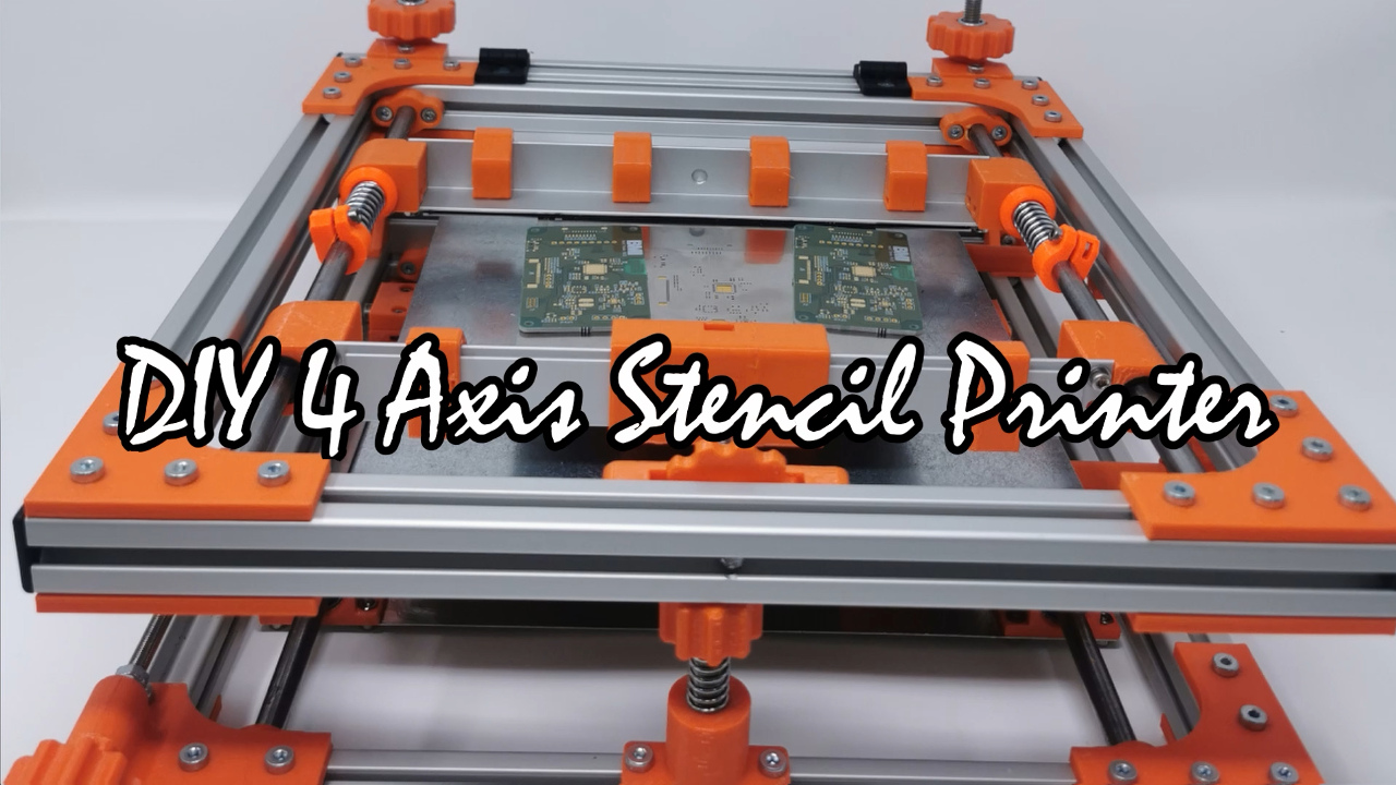


If you prototype a lot of PCBs you may have wished for a stencil printer to speed up your process and get repeatable results. You may find the existing printers quite expensive ( > 2000€). Therefore I decided to take matters in my own hands and design and build a 4-axis stencil printer myself. In the next paragraph you’ll find a brief description of the outcome.This post describes my 3D printed 4-axis pcb stencil printer
Updates
There is a Version 2 up on Thingiverse now: https://www.thingiverse.com/thing:5690704
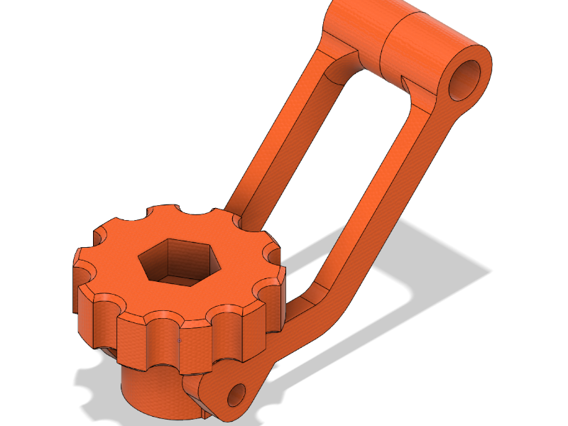
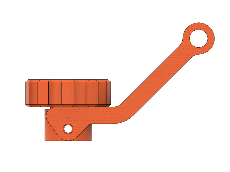
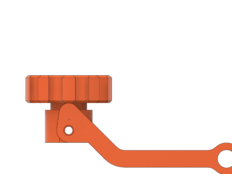
Alex (see comments) made me aware that there could be an additional feature. When lifting ip the upper frame the first few millimeters should reassemble a linear movement so I’ve decided to implement this via an addon. So an eccenter it is.
Design
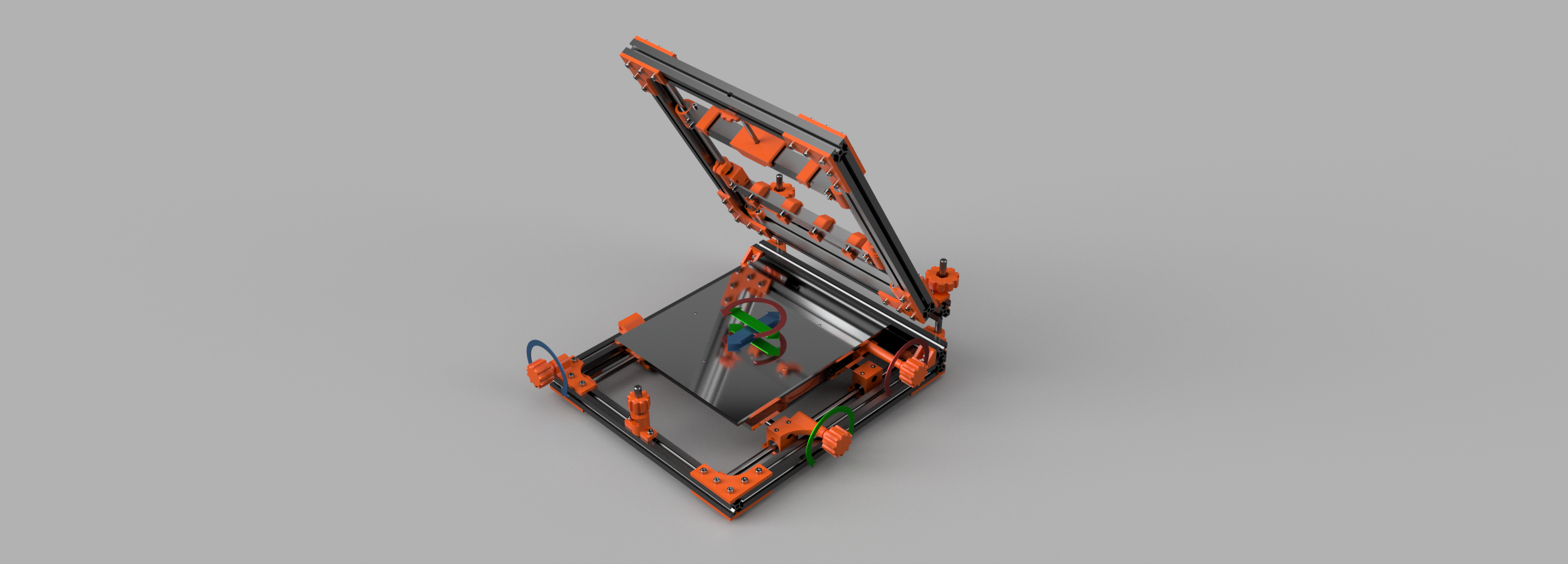
The basic idea is very simple and is heavily relying on well established XYZ-tables. The x- and y-axis move the PCB relative to the stencil while the z-axis adjust the gap between those two. To adjust the angular alignment of PCB and stencil an rotational axis is necessary. It rotates the PCB underneath the stencil on the xy-plane. Finally there has to be a clamping and tension mechanism in order to securely hold the stencil in place.
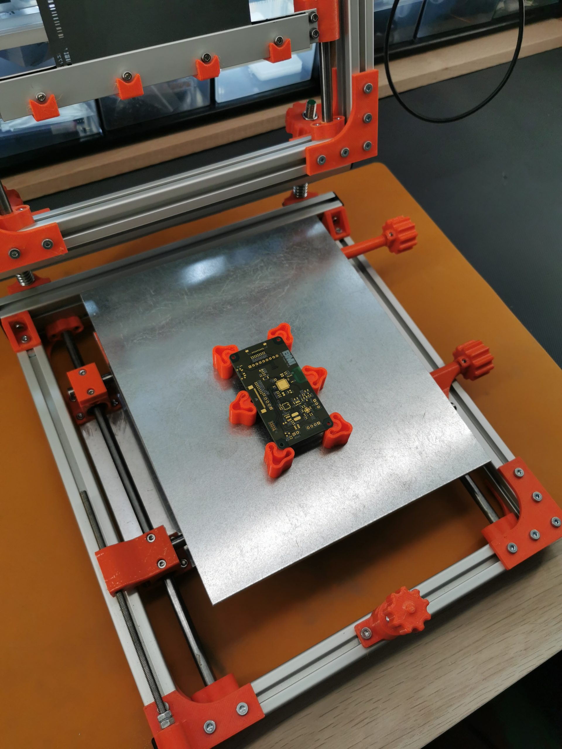
To keep the cost of the printer reasonable widely available parts have to be used. As in 3D printers 8 mm rods and linear bearings seem the obvious choice for the stencil printer, too. Axis movement is achieved with M5 threaded rods for fine control due to its 0.8 mm pitch. The whole design is basically split in two parts. The lower part features the x and y axis as well as the planar rotation axis alpha with the mounting bed for the PCB. The upper part is responsible for the stencil clamping and tension mechanism. For convenience it features a hinge to flip the frame up for easy and fast stencil mounting and pcb placement and removal. The connection between those two parts is designed with spring loaded 8 mm rods for z axis adjustments. Usually the z axis is aligned once in a way that the stencil is sitting flush with the pcb surface and then secured and never touched again. Therefore a low-tech solution is reasonable here. Another feature commercial stencil printers sometimes have is a magnetic bed with standoffs for easy pcb mounting which can easily be implemented with a sheet of galvanised steel and 6 mm cylindrical neodym magnets for the standoffs. The outcome of the considerations above can be seen in the following render shots of the final design.


The basic components can be summarised as follows:
- 2020 aluminium extrusion for the frame
- 8 mm rails and bearings (LM8UU) for the x axis, y axis and the clamping mechanism
- M8 stainless threaded rods for z axis actuation
- M5x0.8 stainless threaded rod for x and y axis actuation
- M3/M4 nuts and screws
- l-profile aluminium extrusion for the clamps with SBR rubber pads for better stiction
- springs for preloading
- 6 mm thick aluminium plates for the bottom plate and the bed for easy working
- galvanised steel sheet for the magnetic bed
- 3D printed parts are from PETG filament and shown in orange
In the following paragraphs some of the components and design choices are described in more depth.
Rotational Axis
As it turns out one of the most expensive (and in this case overkill) parts is the slewing ring to rotate the mounting table with its magnetic bed. These, at least with tolerable play, easily cost more than the other components together. Instead of using a slewing ring I settled on another solution.
The design basically consists of two concentric rings forming a groove for four radial bearings (605zz) to run in. The bearings are mounted on the bottom plate. The outer ring, mounted on the top aluminium plate, is equipped with a partial gear. On the bottom plate a worm gear is held on a M5 threaded rod which provides some flexibility and therefore puts a slight preload on the gears. As it turns out the design works really well and is very inexpensive by utilising only four radial bearings.
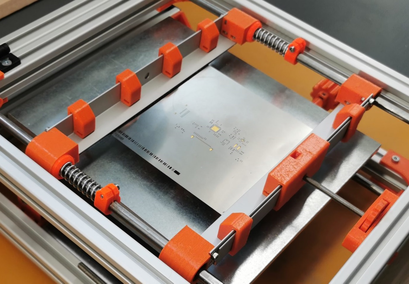
Clamping
Another critical feature is the clamping mechanism. If you order your PCBs at your manufacturer of choice you order a stencil along with them. Usually the stencil is a laser cut stainless stell sheet with a thickness of approx. 100 um. These stencils can be prone to kinking. Therefore the clamping mechanism should be design in a way to firmly hold the stencil while avoiding damage. The design of the clamps is very basic. Each of the two clamps can move independently along two 8 mm rails on linear bearings. The clamp itself consists of two linear aluminium profiles in L-shape to provide some rigidity. While the upper profile is mounted to the bearing carriers on each side the bottom profile is mounted to the upper profile with M3 screws and nuts alongside nut holders for easy tightening. the upper clamp holds a strip of quite tacky SBR rubber to enforce stiction. The lower clamping assembly is attached to a M5 threaded rod which is also attached to the frame and a wheel with a nut to tighten the clamping mechanism once the stencil is clamped firmly. The upper clamping assembly is then held against two springs and tighteners on the rails. So the stencil will not be damaged as easily due to the springs absorbing some of the force when overloaded.
Demo
Below there is a video demo of the handling. If you are interested in building one yourself you’ll find the files on thingiverse.
I’ll add a build log as well as the full parts list with plans in the near future.
This is fantastic, thanks for sharing!
Have you considered how vertical / parallel lift might be implemented in a future iteration?
Several commercial machines have this feature to ensure clean parallel seperation of the stencil from the PCB before the pivot. Just a few mm is enough.
Fine pitch PCBs appear to greatly benefit from this feature.
This video shows an example:
https://vimeo.com/234812807
Hello Alex, I saw your comment on thingiverse as well. This is very interesting input and new to me. Maybe I could simply add an eccentric lever beneath the M8 screws for the z-axis? Thank you for your comment, I’ll keep you updated and if you have any idea how to realise the linear lift I would greatly appreciate it!
Thank you!
Philipp
Hey Alex, I’ve implemented your feature and it seems to work well (see Updates on the top of the page). I’ll upload it as optional addition as soon as I had the time to thoroughly test it. Thank you again!
Hi Philipp.
I’m not experienced with mechanical engineering (learning a little recently) so I had to Google what you meant be an eccentric lever. For anyone else looking at these comments this video helps:
https://www.youtube.com/watch?v=9jrhdVD3Szs
Philipp… this is brilliant! I really look forward to your build log / assembly instructions as this is definitely a project I’d like to try to build and learn from.
This is the correct link:
https://www.youtube.com/watch?v=jogqk3J-CiQ
Phillipp– Could you upload the eccenter file when you get a chance?
Hi,
I’m ordering the parts to build one 🙂 Will you update the build log to include this change?
Thank you
Can you share STEP file in place of a build log? Can use it for building reference and you won’t have to write any instructions.
Hey Duke, there will be a full (virtual) build log as well as the step files. Unfortunately I’ll need some time.
Philipp
Hi Philipp! Thanks for the reply! Looking forward to seeing your build log. Cheers!
Hello could u pls send instruction od assemblng and usage for 4-Axis PCB Stencil Printer – 3D printed. My mail: britani.connors@gmail.com. Thank you in advance.
Interesting. 1515 and 1010 extrusion are more readily available for me (see: OpenBeam / MakerBeam).
Would you publish a precise full parts list / breakdown? I’d like to consider scaling this down for 1515 profile for myself.
Hey Joan, thank you for your comment. I’ll get back to this project as fast as possible. At the moment I’m busy working on another project for a customer. Thank you for your patience.
Hey.
Very nice design.
I am planning to build it.
You can upload a BOM file.
With him it will be clearer what is what and how much.
thank
Hi Philipp. I know you are busy on other projects. I just wondered if you had any idea when you might share BOM and/or full build log so I know when to check back… is it likely to be a few days or a few weeks at the moment?
Hi Philipp. I know it is now you have to focus on your day job first but I wonder if you have a timeframe for when you expect to release assembly instructions? My first 3D printer finally arrived and now I am keen to try this build.
Hi Philipp,
I would like to build it also. Is there the possibility to know at least the size of the non-3d-printed parts like extrusions and rails).
I ned the data tu buy the parts…
Thanks
Gabi
Hi Philipp, a beautifully designed piece of equipment that I’d like to copy. Certainly understand that developing instructions can itself be a significant task. Maybe if you were able just to put up a few more photos and/or diagrams with dimensions to start, it would be enough to help make something similar.
Cheers Ron.
Really nice design, really looking forward to the build instructions! Thanks for sharing!
I began to write the build log: https://dengler-mechatronik.de/?p=790
Thanks for the update. I’m going to build one for myself as well 🙂
Cool stencil printer. Any update on releasing the bill of materials? Thanks!
Started a bill of materials based off scaling from the parts and images and a bit of guesswork here:
https://docs.google.com/spreadsheets/d/1A7Fg_CgfPcbLEn5Zp_6HpfGlA350f67ehTiDADjn61A/edit?usp=sharing
Comments should be open on it if you see something I missed or got wrong.
I began to write the build log: https://dengler-mechatronik.de/?p=790
Hi again Philipp, my 3D printer is working again 🙂 so I am ready to try and build this.
Can you upload the STL for the eccentric lever add-on to thingiverse? Thanks!
Hello
can i get a project in step file for to resize the printer to fit my needs?
Wanted to stop by again and say that the stencil printer has turned out great. Thank you so much for sharing the plans!
Wire’s BOM was almost perfect, though it’s a bit under on some things and a bit over on others. I’ll try and get my notes and photos online soon. Finding the springs was the hardest part, as McMaster-Carr will not ship outside the US and other retailers wanted something stupid like $14 a spring. No thanks! I ended up ordering a few spring assortment “grab bags” and finding what I needed.
I recommend printing all parts in a stronger material than PLA. I ended up using PETG, but PC or ABS would also work. The part most prone to failure is the housing for the stencil tensioner gear at the front. I may end up redesigning this part to have a thicker wall on the side facing the stencil, at the expense of reducing max possible stencil size.
My only real complaint is that the worm gear for the alpha axis has a lot of backlash/slop, meaning the bed can and will rotate when opening/closing the lid or applying pressure with a squeegee. I’ve had to work around this by locking 2x nuts to each other on each side of the worm gear to hold it in place. I toyed with gluing the worm gear to its threaded rod, but that would make assembly/disassembly very difficult.
I’m keen to see how the eccentric mod would work on the lifter. That might help get the additional accuracy the device needs to deal with very fine pitch pads (such as QFN, which I can’t reliably stencil with this setup).
Thanks again – great work!