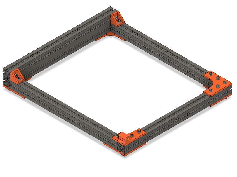
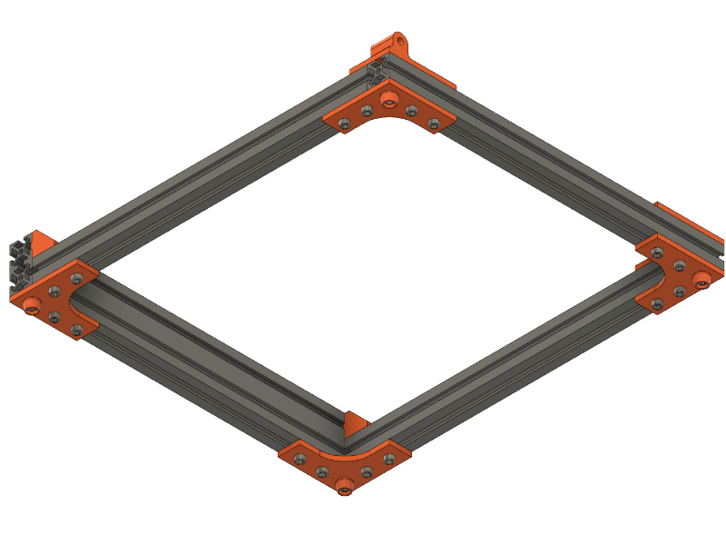
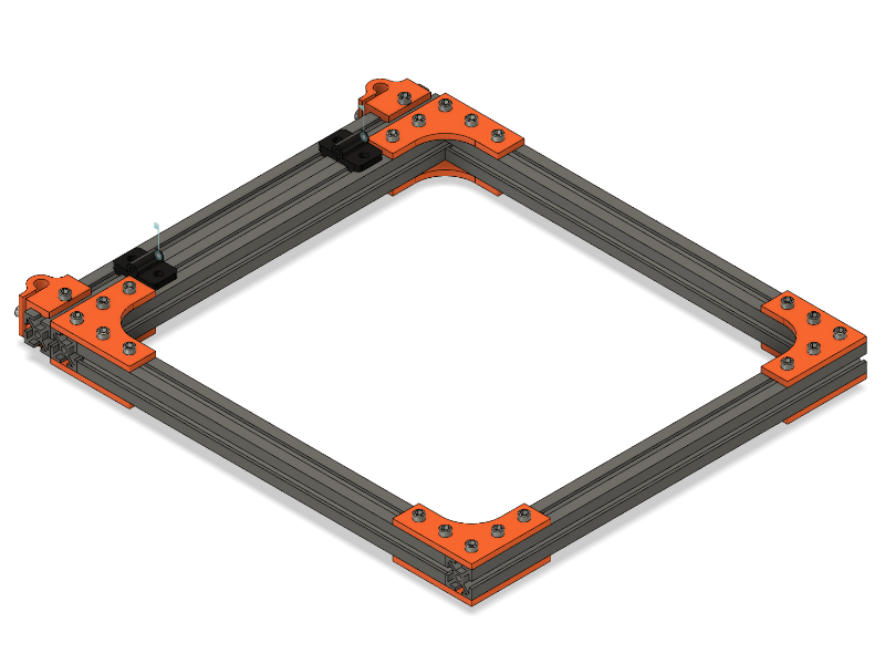
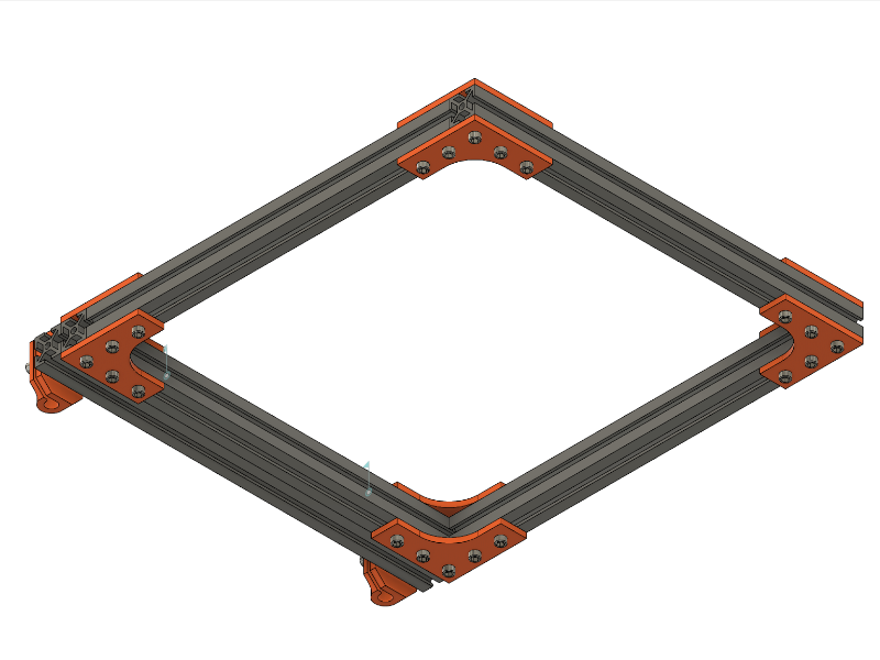
STEP 1: Bottom Frame
| Count | Name |
| 1 | Aluminum Extrusion 2040 x 300 |
| 3 | Aluminum Extrusion 2020 x 300 |
| 5 | (3DP) BOT_BRACKETS |
| 1 | (3DP) BOT_BRACKET_X_AXIS |
| 2 | (3DP) BOT_RIGHT_ANGLE_CON |
| 4 | (3DP) STAND |
| 32 | Screw DIN 912 M4x10 |
| 32 | Nut f. Extrusion 2020 |
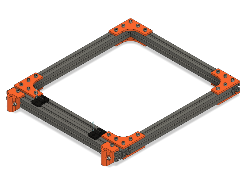
STEP 2: X-Axis Carriage


| Count | Name |
| 2 | Linear Rail 8mm x 300mm (X-Rails) |
| 2 | Linear Rail 8mm x 244mm (Y-Rails) |
| 4 | (3DP) BOT_RAIL_HOLDER |
| 4 | (3DP) BOT_BEARING_MOUNT_X_AXIS |
| 8 | LM8UU Linear Bearing |
| 16 | Screw DIN 912 M3x6 |
| 24 | Nut DIN 934 M3 |
| 8 | Screw DIN 912 M4x10 |
| 8 | Nut f. Extrusion 2020 |
| 1 | Thin Aluminum Plate (1-2mm) 257mm x 162mm |
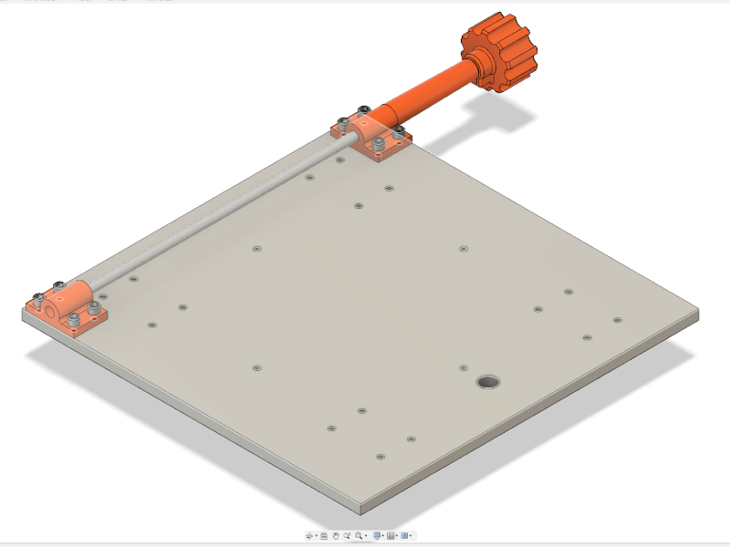
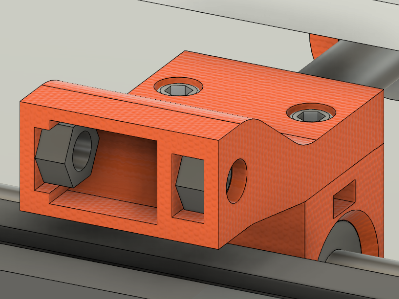
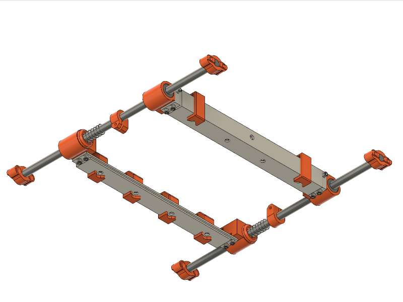
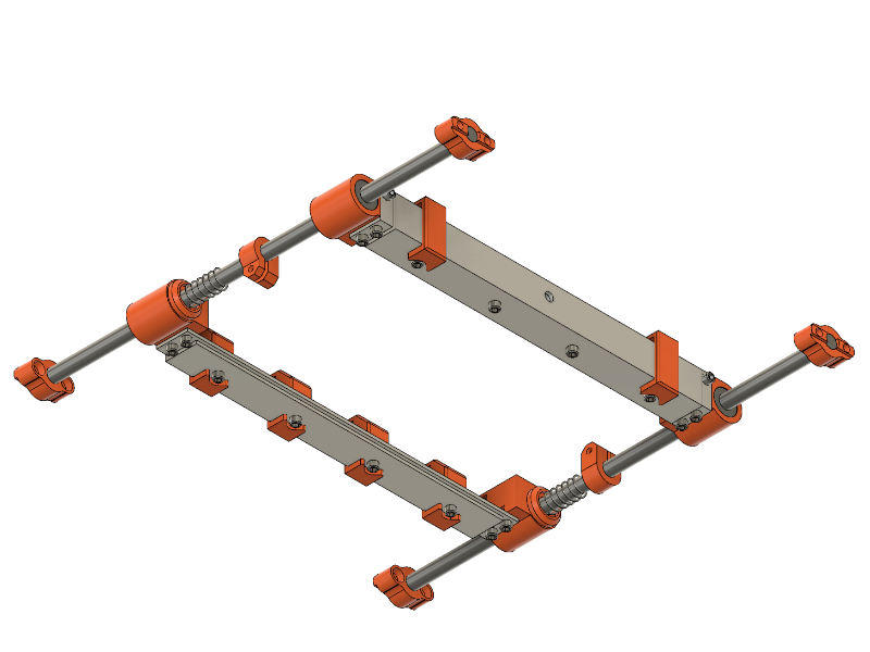
STEP 3: Aluminum Plates and Bearing Preparation
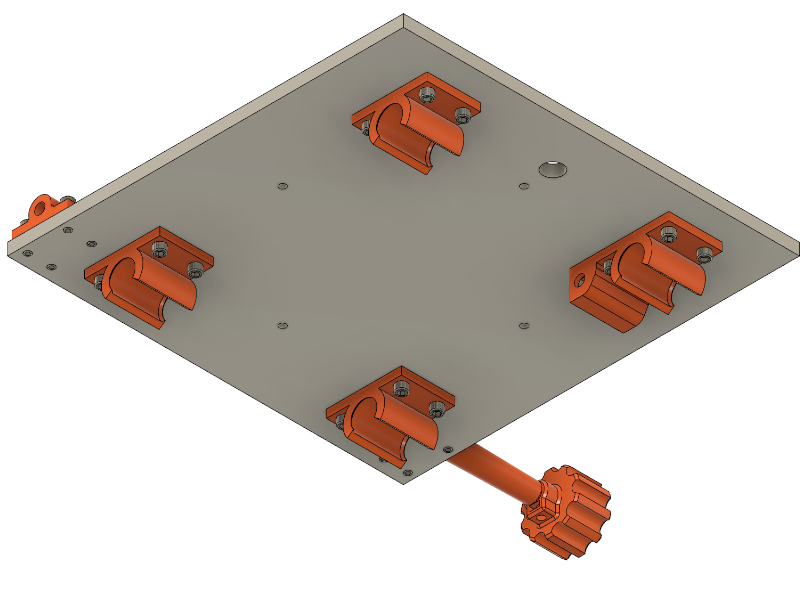
| Count | Name |
| 1 | Aluminum Plate 200x200x6 (Drawing below) |
| 1 | Threaded Rod M5x270 |
| 24 | Screw DIN 912 M3x8 |
| 1 | Nut DIN 934 M3 |
| 1 | Set Screw M3x6 |
| 3 | (3DP) BOT_BEARING_MOUNT_Y_AXIS |
| 1 | (3DP) BOT_BEARING_MOUNT_Y_AXIS_DRIVEN |
| 1 | (3DP) BOT_ROD_HOLDER_ALPHA_AXIS_SHORT |
| 1 | (3DP) BOT_ROD_HOLDER_ALPHA_AXIS |
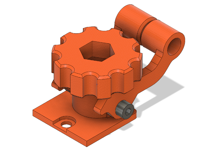
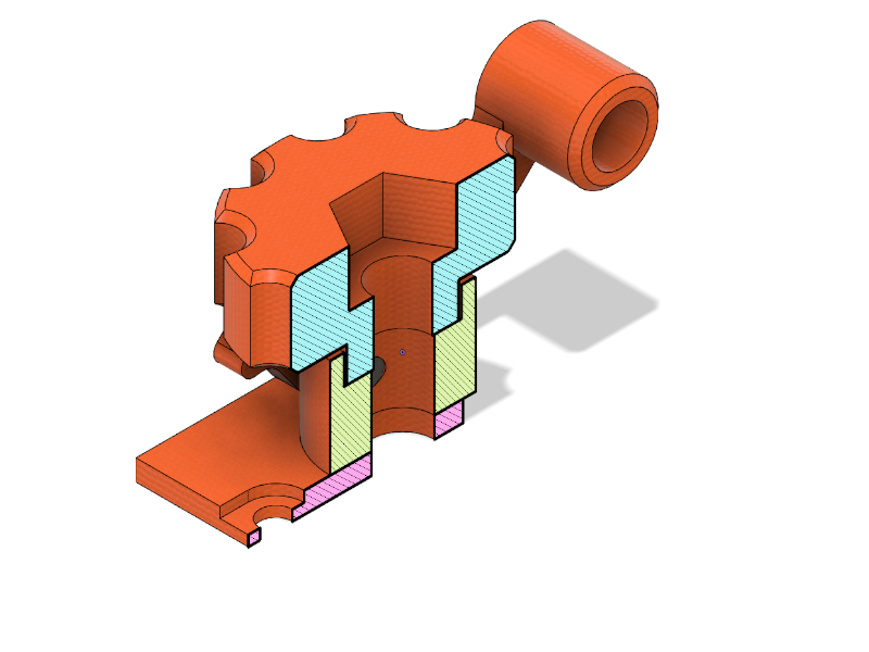
| 1 | (3DP) BOT_HANDWHEEL |
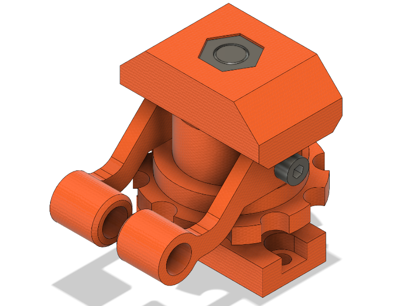
STEP 4: Alpha Axis Bearing
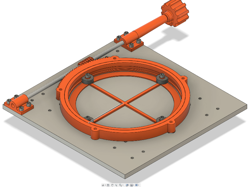
| Count | Name |
| 1 | Aluminum Plate (Upper) 200x240x6 (Drawing below) |
| 9 | Screw DIN 912 M3x14 |
| 4 | Bearing 14x7x5 |
| 1 | (3DP) SR_BEARING_PLATE |
| 1 | (3DP) SR_WORM_GEAR |
| 1 | (3DP) SR_INNER_RING |
| 1 | (3DP) SR_OUTER_RING_W_GEAR |
| 4 | (3DP) Adapter D5 to M3x14 |
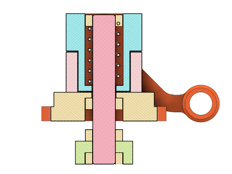
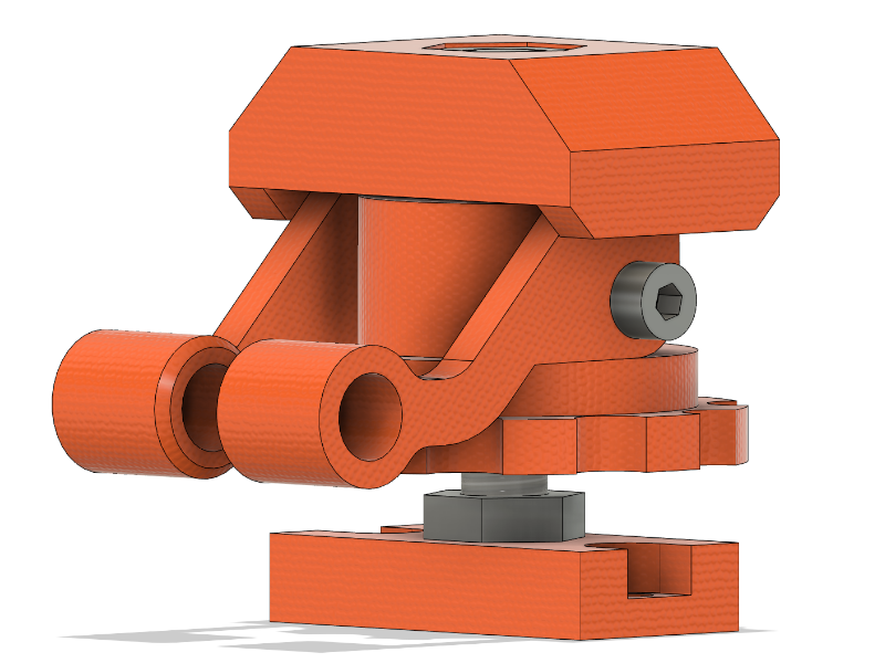
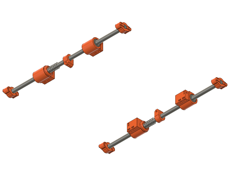
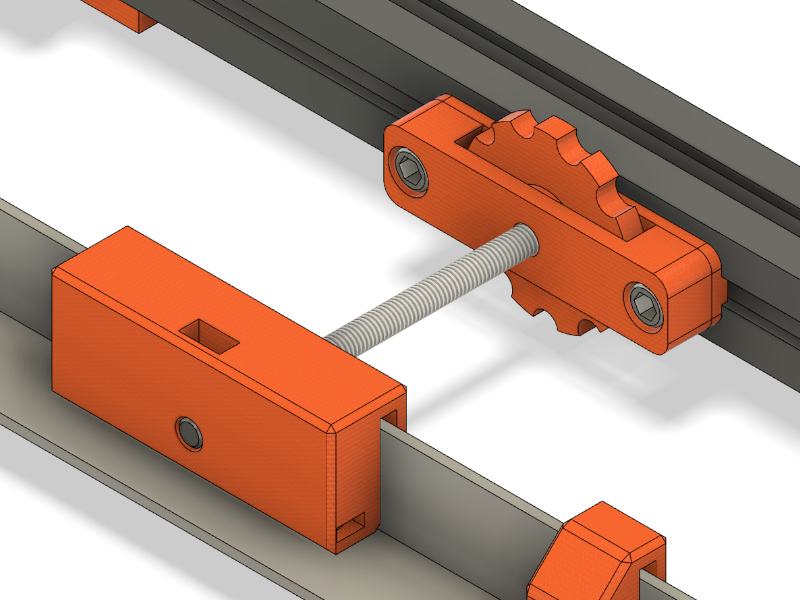
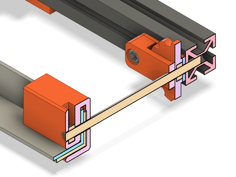
STEP 5: Spring Loaded Drive Assembly
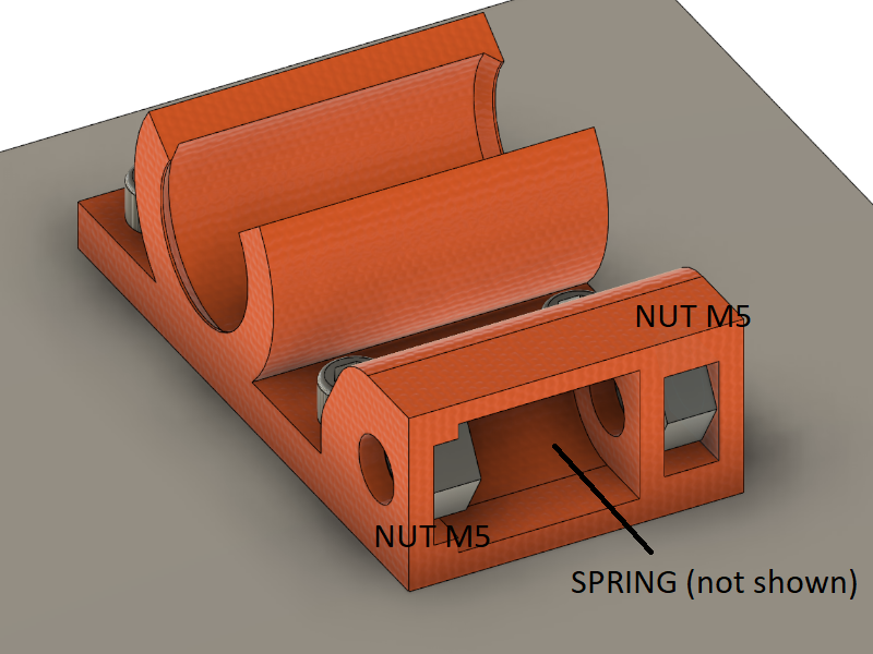
Insert two M5 nuts as shown. Insert the spring and washers if necessary. The spring has to be preloaded in order to eliminate axial play.
| Count | Name |
| 1 | Spring (ID min. 6mm) |
| 2 | Nut DIN 934 M5 |
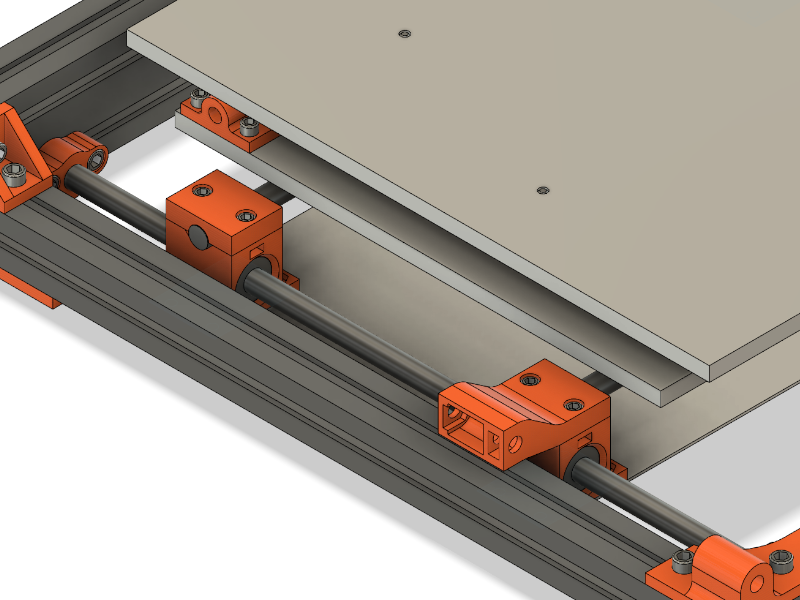
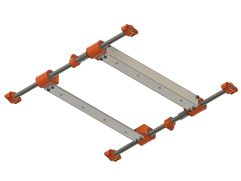
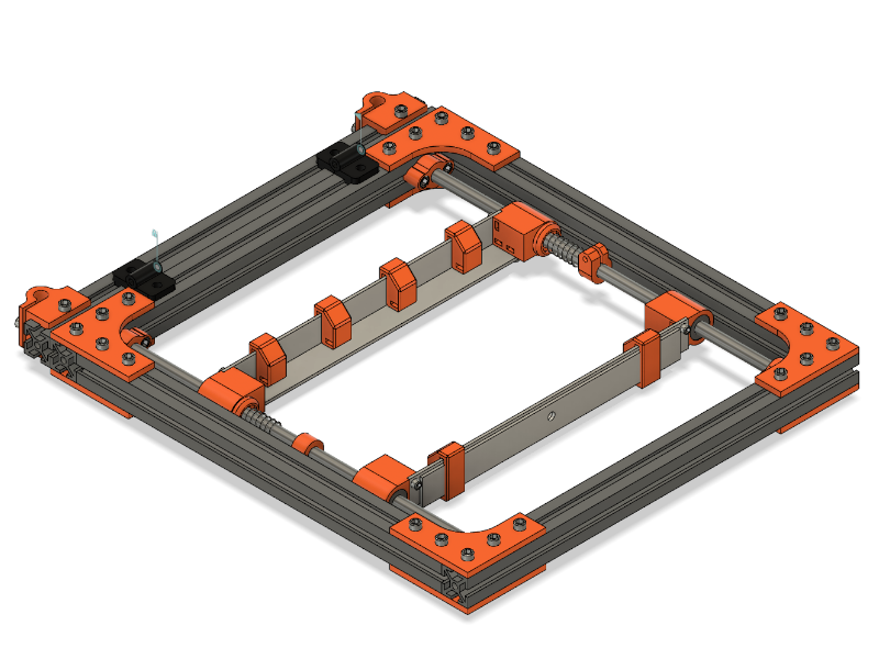
STEP 6: Clip in Alpha Axis Assembly
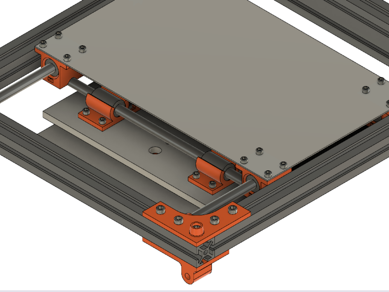
Clip the Alpha Axis Assembly to the LM8UU bearings of the bottom frame.
STEP 8: Spring Loaded X Axis
Assemble according to Step 5.
| Count | Name |
| 1 | Spring (ID min. 6mm) |
| 2 | Nut DIN 934 M5 |
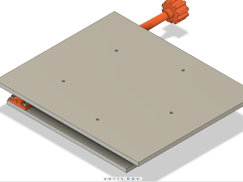
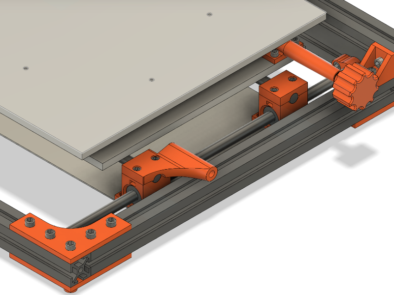
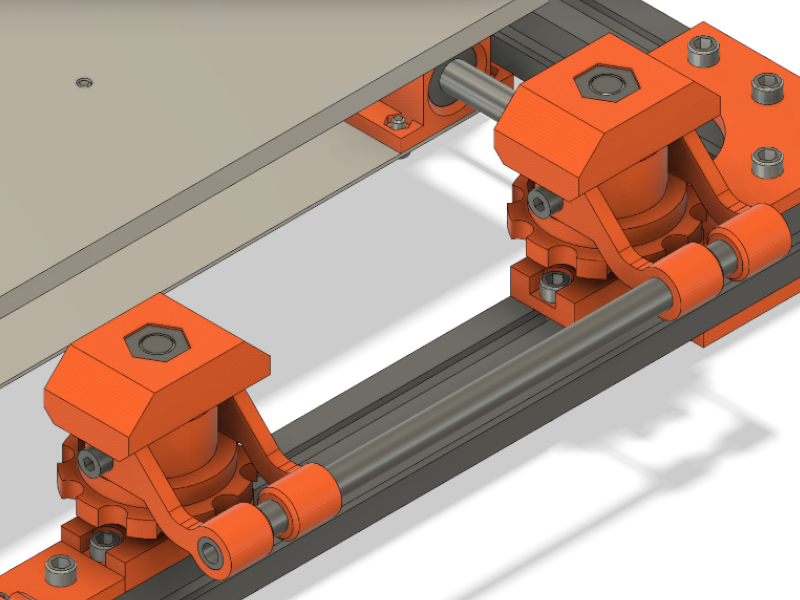
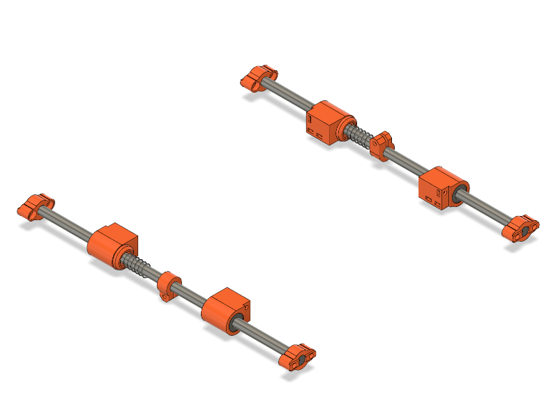
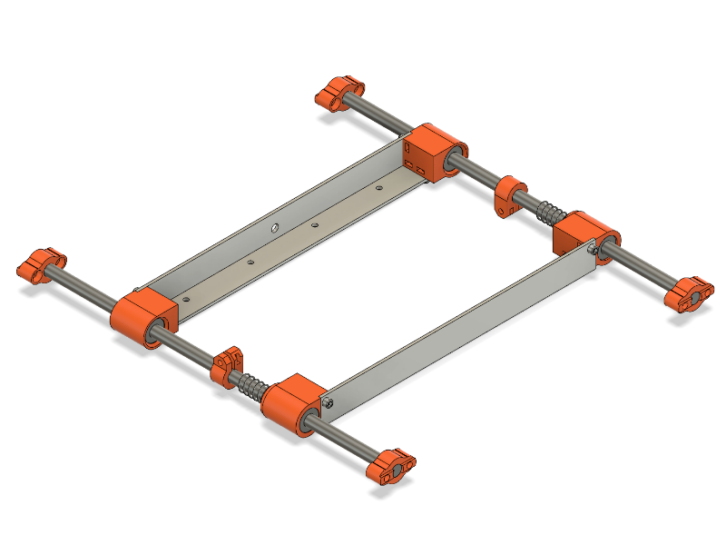
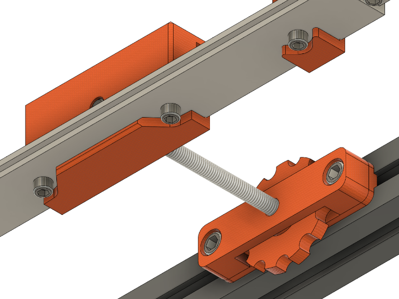
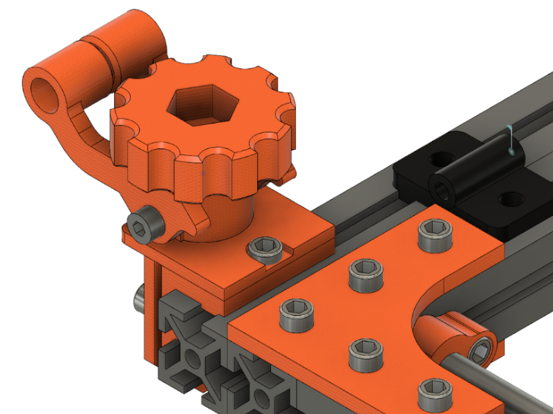
STEP 9: X and Y Axis Drive Assembly
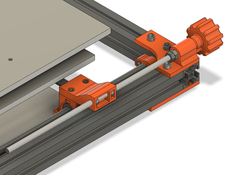
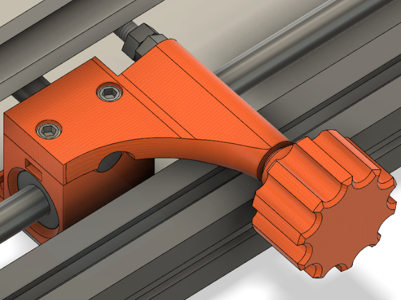
Thread the M5 rods through the spring laoded x- and y-axis drives and add two M5 nuts before the 3D-printed holders in order to secure against pulling the rods out. Tighten the pair of respective M5 nuts against each other. Add a M3 nut to each of the BOT_HANDWHEELS’s slots and secure the handwheels to the end of the rods by tightening the M3 set screw.
| Count | Name |
| 4 | Nut DIN 934 M5 |
| 2 | Nut DIN 934 M3 |
| 2 | Set Screw M3x6 |
| 2 | Threaded Rod M5x270 |
| 2 | (3DP) BOT_HANDWHEEL |
STEP 10: Z-Axis Clamp Assembly

Insert the nuts into the profile, align the clamps and tighten the srews.
| Count | Name |
| 8 | Screw DIN 912 M4x10 |
| 8 | Nut f. Extrusion 2020 |
| 2 | Threaded Rod M8x140mm |
| 2 | (3DP) BOT_CLAMP_Z |
STEP 11: Eccenter Front
Assemble two eccenters as shown. The bottom nuts mount the M8 threaded rod to the base.
| Count | Name |
| 8 | Screw DIN 912 M4x10 |
| 4 | Nut f. Extrusion 2020 |
| 8 | Nut M8 DIN439 |
| 2 | Threaded Rod M8 L=55mm |
| 2 | Spring (ID > 9mm) |
| 1 | Handlebar (e.g. aluminum pipe) OD = 8mm |
| 2 | (3DP) ECCF_HEIGHT |
| 2 | (3DP) ECCF_MOUNT |
| 2 | (3DP) ECCF_LEVER |
| 2 | (3DP) ECCF_TOP |
| 2 | (3DP) ECCF_BOT |
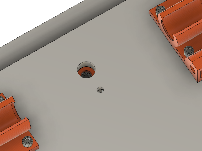
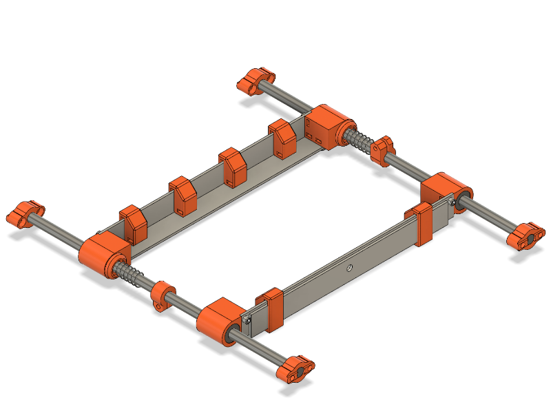
STEP 14: Aluminum Profiles
Please note that one of the profiles has an additional hole for an linear drive shaft. You may want to drill that hole later during final assembly. Insert the M3 nuts into the according slots and tighten the profiles to the 3D-printed parts.
| Count | Name |
| 12 | Screw DIN 912 M3x10 |
| 12 | Nut DIN 934 M3 |
| 2 | L-shaped aluminum extrusion |
STEP 16: Top Frame / Axis Assembly
| Count | Name |
| 8 | Screw DIN 912 M4x10 |
| 8 | Nut f. Extrusion 2020 |
STEP 18: Final Assembly
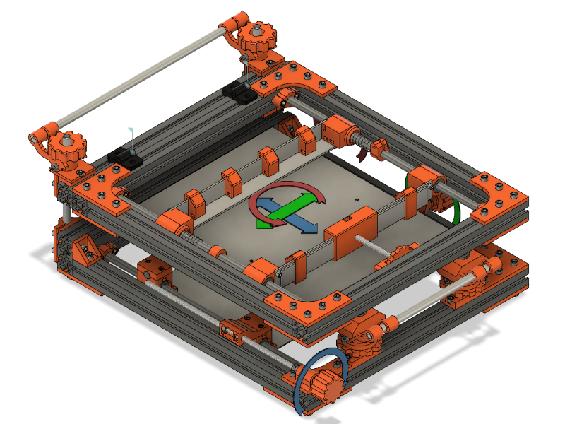
Assemble two eccenters as show. Tighten these to the top frame. Mount the top frame to the bottom frame assembly. Finally adjust the height of the top frame to fit your pcb holders and general setup.
| Count | Name |
| 4 | Screw DIN 912 M4x10 |
| 8 | Nut M8 DIN439 |
| 2 | Threaded Rod M8 L=55mm |
| 1 | Handlebar (e.g. aluminum pipe) OD = 8mm |
| 2 | (3DP) TOP_HANDWHEEL_Z_AXIS |
| 2 | (3DP) ECCB_BODY |
| 2 | (3DP) ECCB_LEVER |
| 2 | (3DP) ECCB_SHIM |
Thank you so much for publishing this!
I have been visiting your site regularly to see if you’d had chance to publish the build log, whilst appreciating that you must be very busy with your day job. It really is very generous for you to share your hard work so others may build their own stencil printer.
This is an excellent project and I can’t wait to build my own!
Thanks again 🙂
Hi,
Thank you for start the build log 🙂 Could you post a BOM so we can start to order the materials?
Hi,
could you add the size of Aluminum Extrusion?
Thank you
Hey Jose, thanks for your comment. Added a new step and updated the extrusion size. Thank you!
Thanks for the updates!
Hi,
thank you for this awesome construction.
I’m printing all the stuff at the moment. But I couldn’t find the 3d model for ‘ Adapter D5 to M3x14’.
Is it really missing or is it a standard item that can be downloaded elsewhere?
Thank you very much for the work!
Want to build it!
Do you have plans to continue build log with upper frame description?
If you want, i can make report about my build of your design, when it will be finished.
Hello. Amazing work, build one now. Can you post your pcb holders stl to thingiverse pls.
Hello Admin,
the project is really helpful and I’m in the process of building this,
can you share the build log building the top frame as well
Are on your plans release the full documenation?
Hello Dengler,
Amazing job on building and sharing this very nice stencil printer! it’s looking really good!
Hopefully you have been using it yourself too 😀
I am trying to order the parts for the printer (already started some 3D printing), but I was wondering if you have any documentation on the top frame/stencil holder? It looks fairly similar to the bottom frame combined with the x-axis carriage but I do notice subtle changes here and there.
Thanks again, great work on the design!
Hi, thanks for this great project! The part “Adapter D5 to M3x14” is not available in the 3D files on Thingiverse. Could you please upload it? Thank you!